Search form
- (888)-777-4647


(0)
(0)-
Express Checkout


- Location


North America
Europe
Asia
Central & South America
Africa & Middle East
Pacific Rim
 Sign Up/Log In
NORTH AMERICA
- USA English-en
- Canada English-en
- Mexico Spanish-es
EUROPE
- France French-fr
- Germany Deutsch-de
- Italy Italian-it
- Spain Castellano-cas
- UK/Ireland English-en-gb
- All Other European Countries English-en-gb
ASIA
- China Chinese-zh-hans
- All Other Eastern Asian Countries Chinese-zh-hans
- India English-en-gb
- All Other Indian Subcontinent Countries English-en-gb
CENTRAL & SOUTH AMERICA
- Carribbean Countries English-en
- Suramerica y Centroamerica Spanish-es
AFRICA & MIDDLE EAST
- All African Countries English-en-gb
- Israel English-en-gb
- All Middle East Countries English-en-gb
Pacific Rim
- Australia / New Zealand English-en-gb
- All Other Pacific Rim Countries English-en
There are no products in your shopping cart.
| 0 Items | Total: $0.00 |
Stock Spring Tolerances and Engineering Notes
Imperial/Metric Conversions
Force
| To Convert Newtons to | Kilogrammes | Pounds |
| Multiply by | 0.102 | 0.22487 |
| To Convert Kilogrammes to | Newtons | Pounds |
| Multiply by | 9.807 | 2.2046 |
| To Convert Pounds to | Newtons | Kilogrammes |
| Multiply by | 4.448 | 0.4536 |
Rate
| To Convert kg/mm to | lb/in | N/mm |
| Multiply by | 55.998 | 9.807 |
| To Convert lb/in to | kg/mm | N/mm |
| Multiply by | 0.017858 | 0.175133 |
| To Convert N/mm to | kg/mm | lb/in |
| Multiply by | 0.101968 | 5.7099 |
Length
| To Convert Inches to | Meters | Feet | Millimetres |
| Multiply by | 0.0254 | 0.08333 | 25.4 |
| To Convert Millimetres to | Meters | Feet | Inches |
| Multiply by | 0.001 | 0.003281 | 0.0393701 |
Stock Compression Spring and Extension Spring Engineering Notes and Tolerances
General Notes
Direction of Wind
Left or Right at Lee Spring’s Discretion
Compression Spring Ends
- Squared and ground (squareness within 3°:Standard Springs (LC, LCM), Heavy Duty Springs (LHC), High Pressure (LHP), DIN-PLUS Part 1
- Squared, Not Ground: Bantam Mini Compression Springs (CB, CBM), Instrument Springs (CI, CIM), Lite Pressure Springs (LP), DIN-PLUS Part 2
Extension Spring Ends
- Full diameter at random position, except those LEM products designed to meet DIN 2097 Standards
- Loop openings are approximately one wire diameter.
Stock Compression Outside Diameter (OD) Tolerances*
Imperial/Inch
| .025" | to | .039” | ± | .002” |
| .040” | to | .118” | ± | .003” |
| .120" | to | .250” | +.003” / –.005” | |
| .251” | to | .299” | ± | .005” |
| .300” | to | .500” | ± | .008” |
| .501” | to | .850” | ± | .015” |
| .851” | to | 1.125” | ± | .020” |
| 1.126” | to | 1.218” | ± | .025” |
| 1.250” | to | 1.460” | ± | .030” |
| 1.480” | to | 1.687” | ± | .040” |
| 1.937" | to | 2.000" | ± | .055" |
Metric
| 0.64mm | to | 0.99mm | ± | .05mm |
| 1.02mm | to | 3.00mm | ± | .08mm |
| 3.05mm | to | 6.10mm | +.08mm / –.13mm | |
| 6.38mm | to | 7.59mm | ± | .13mm |
| 7.62mm | to | 12.70mm | ± | .20mm |
| 12.73mm | to | 21.59mm | ± | .38mm |
| 21.62mm | to | 28.58mm | ± | .51mm |
| 28.60mm | to | 30.94mm | ± | .64mm |
| 31.75mm | to | 37.08mm | ± | .76mm |
| 37.59mm | to | 42.85mm | ± | 1.02mm |
| 49.20mm | to | 50.80mm | ± | 1.40mm |
Spring rate: ± 10% ; Solid Height Tolerance: +5%, no lower limit
*Except where noted to meet DIN 2098
This O.D. table not applied to Lite Pressure, HEFTY Die, REDUX, or MIL-SPEC
Stock Lite Pressure (LP Series) Outside Diameter (OD) Tolerances
Imperial/Inch |
||||
|---|---|---|---|---|
| .201" | to | .300" | ± | .008" |
| .301" | to | .500" | ± | .010" |
| .501" | to | .850" | ± | .020" |
| .851" | to | 1.125" | ± | .025" |
| 1.126" | to | 1.460" | ± | .030" |
| 1.461" | to | 1.687" | ± | .040" |
| 1.688" | to | 1.937" | ± | .055" |
| 1.938" | to | 2.375" | ± | .070" |
| 2.376" | to | 2.875" | ± | .090" |
Metric |
||||
|---|---|---|---|---|
| 5.11mm | to | 7.62mm | ± | .20mm |
| 7.65mm | to | 12.70mm | ± | .25mm |
| 12.73mm | to | 21.59mm | ± | .51mm |
| 21.62mm | to | 28.58mm | ± | .64mm |
| 28.60mm | to | 37.08mm | ± | .76mm |
| 37.11mm | to | 42.85mm | ± | 1.02mm |
| 42.88mm | to | 49.20mm | ± | 1.40mm |
| 49.23mm | to | 60.33mm | ± | 1.78mm |
| 60.35mm | to | 73.03mm | ± | 2.29mm |
Spring rate: ± 10%
Stock MS24585 Compression Outside Diameter (OD) Tolerances
Imperial/Inch |
||||
|---|---|---|---|---|
| .120" | to | .240" | ± | .005" |
| .300" | to | .500" | ± | .008" |
| .550" | to | .850" | ± | .015" |
Metric |
||||
|---|---|---|---|---|
| 3.05mm | to | 6.10mm | ± | .13mm |
| 7.62mm | to | 12.70mm | ± | .20mm |
| 13.97mm | to | 21.59mm | ± | .38mm |
Spring rate: ± 10%
Solid Height Tolerance: Max, no lower limit
Stock Extension Outside Diameter (OD) Tolerances*
Imperial/Inch |
||||
|---|---|---|---|---|
| .063" | to | .098" | ± | .004" |
| .109" | to | .299" | ± | .005" |
| .300" | to | .500" | ± | .010" |
| .501" | to | .850" | ± | .015" |
| .851" | to | 1.125" | ± | .020" |
| 1.126" | to | 1.250" | ± | .030" |
| 1.251" | to | 1.500" | ± | .040" |
| 1.501" | to | 1.750" | ± | .050" |
| 1.751" | to | 2.000" | ± | .055" |
Metric |
||||
|---|---|---|---|---|
| 1.60mm | to | 2.50mm | ± | .10mm |
| 2.77mm | to | 7.59mm | ± | .13mm |
| 7.62mm | to | 12.70mm | ± | .25mm |
| 12.73mm | to | 21.59mm | ± | .38mm |
| 21.62mm | to | 28.58mm | ± | .51mm |
| 28.60mm | to | 31.75mm | ± | .76mm |
| 31.78mm | to | 38.10mm | ± | 1.02mm |
| 38.13mm | to | 44.45mm | ± | 1.27mm |
| 44.48mm | to | 50.80mm | ± | 1.40mm |
Spring rate: ± 10%
*Except where noted to meet DIN 2097 or MIL-SPEC
Stock MS24586 Extension Outside Diameter (OD) Tolerances
Imperial/Inch |
||||
|---|---|---|---|---|
| .120" | to | .240" | ± | .005" |
| .300" | to | .500" | ± | .008" |
| .650" | to | 1.000" | ± | .015" |
Metric |
||||
|---|---|---|---|---|
| 3.05mm | to | 6.10mm | ± | .13mm |
| 7.62mm | to | 12.70mm | ± | .20mm |
| 16.51mm | to | 25.40mm | ± | .38mm |
Spring rate: ± 10%
End Hooks Position: Inline within 22°
Relative Position of End Hook Openings is Factory Optional
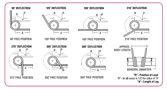
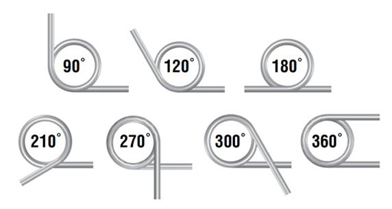
Stock Torsion Engineering Notes and Tolerances
General Notes
-
Lengths of legs are shown as "A" in sketches below.
-
Please note: "R" (radius in inches) where force is applied is always 1/2 of "A" (Length of Leg). Dotted lines of legs show loaded position where values of "T" (Torque) will be achieved at "R" (Radius).
-
To translate torque values to direct load: Use Formula - P = T/R P = Load applied at Radius (R) T = Torque Example: Part LTL 012A 01, what is the load where R = .187? Using P = T/R = .050/.187 = .267lbs.
-
To calculate torque values other than those listed (Position of Ends), a direct proportion may be used. Example: Part LTL 012 A 01. Torque shown in catalogue listing is .050 in-lbs. for 90° deflection; therefore, torque for 45° would be .025 in-lbs.
-
Inspection of Load - Loads should always be checked at the Radius ("R" value)
-
Mandrel Size: Generally, torsion springs are used over a mandrel (shaft or arbor). The column "Suggested Mandrel Size, Inches", allows approximately a 10% clearance for the various deflections shown in examples below. If you require greater deflections, we suggest a suitable reduction in the mandrel size.
-
Direction of Wind: Good design dictates that torsion springs should be used in the direction that winds the coil. When ordering be sure to choose either LTL (Left Hand Wound) or LTR (Right Hand Wound) for required application.
Stock Torsion Outside Diameter (OD) Tolerances
Imperial/Inch
| .093” | to | .125” | ± | .004” |
| .126” | to | .200” | ± | .005” |
| .201” | to | .300” | ± | .007” |
| .301” | to | .410” | ± | .010” |
| .411” | to | .500” | ± | .013” |
| .501” | to | .700” | ± | .015” |
| .701” | to | .875” | ± | .020” |
| .876” | to | 1.125” | ± | .025” |
| 1.126” | to | 1.218” | ± | .030” |
| 1.219” | to | 1.250” | ± | .035” |
| 1.251" | to | 1.360" | ± | .040" |
| 1.361" | to | 1.520" | ± | .045" |
| 1.521" | to | 1.750" | ± | .050" |
| 1.751" | to | 2.000" | ± | .055" |
| Over 2.000" | ± | .060" |
Metric
| 2.36mm | to | 3.17mm | ± | .10mm |
| 3.18mm | to | 5.08mm | ± | .13mm |
| 5.09mm | to | 7.62mm | ± | .18mm |
| 7.63mm | to | 10.41mm | ± | .26mm |
| 10.42mm | to | 12.70mm | ± | .33mm |
| 12.71mm | to | 17.78mm | ± | .38mm |
| 17.79mm | to | 22.23mm | ± | .51mm |
| 22.24mm | to | 28.58mm | ± | .64mm |
| 28.59mm | to | 30.94mm | ± | .76mm |
| 30.95mm | to | 31.75mm | ± | .89mm |
| 31.76mm | to | 34.54mm | ± | 1.02mm |
| 34.55mm | to | 38.60mm | ± | 1.14mm |
| 38.61mm | to | 44.45mm | ± | 1.27mm |
| 44.46mm | to | 50.80mm | ± | 1.40mm |
| Over 50.80mm | ± | 1.52mm |
Stock REDUX Wave Spring Engineering Notes and Tolerances
Torque: ± 10%
Tolerances on Free Position:
From 3 to 10 total coils (Incl.) ± 10°
From 11 to 20 total coils (Incl.) ± 15°
Stock REDUX Wave Spring Engineering Notes and Tolerances
General Notes
-
Stock REDUX Wave Springs are made of material 17-7PH Stainless Steel
-
Maximum operating temperature is 650 degrees F
-
Nominal Load is the approximate force at the Working Height. Be advised springs may take a set if compressed below the Working Height.
-
The Number of Turns comprises a continuous coil; there is no welding or adhesive between waves.
-
Ends turns are regular & wavy. Flat & shim ends can be offered in a special order.
Stock REDUX Wave Spring Tolerances
Rate: ± 25%
The Outside Diameter and Inside Diameter are reference only. REDUX Wave Springs are manufactured to operate with the specified mating Hole Diameter and Rod Diameter.
Why Choose Lee Spring?
Selection
25,000+ products
available, plus custom
products made to your specification.
FREE Standard Ground Shipping
on Stock Springs in the Continental United States
FREE Plating
on all Music Wire Stock Springs
FREE Grinding
on all Standard Stock Compression Springs
In Stock
Springs ready to ship
today.
Expert Engineering Assistance
on Stock and Custom Springs
Certificate of Compliance
on all Stock Springs and Custom Springs
Guaranteed RoHS Compliance
on all Stock Springs
Support
Engineering and
Customer Service teams ready to assist.
Live Customer Service Support
at all Locations
Enhanced CAD Downloads
on Stock Springs Designs
Global Flexibility
allows Lee Spring to find solutions that meet your
geographic requirements wherever your business
takes you in the world
Social Icon


.png "Lee Spring Logo")